 Simulation Software for Fluids and Solids
Simulation Glass Floating
Simulation of glass floating is one of many glass simulation applications and can excellently be performed with the CFD software NOGRID points. This simulation software supports the production of high-quality, defect-free glass products by enabling targeted optimization of the floating process.
Production of float glass
Float glass is manufactured by continuously pouring molten glass onto a bath of molten tin. The molten glass spreads over the tin surface, forming a consistently flat, high-quality sheet of glass that is later heat-polished. This method produces glass free from waves or distortions and has become the global standard for flat glass production - over 90% of the world production of flat glass is float glass. The float glass process was developed by Sir Alastair Pilkington and patented by Pilkington in 1959. The detailed history of its development was presented by Sir Alastair Pilkington in his 1969 review lecture to the Royal Society of London (Pilkington, L.A.B. Proc. Roy. Soc. London 1969, A314, 1-25).

Figure 1: Float process
When molten glass is poured onto a bath of clean molten tin, it spreads out much like oil on a water surface. In this process, gravity and surface tension cause the top and bottom surfaces of the glass to become nearly flat and parallel. However, the molten glass does not spread indefinitely over the surface of the molten tin. Despite the force of gravity, surface tension between the glass and the tin limits the spreading. The resulting equilibrium between the gravitational forces and the surface tension determines the equilibrium thickness (T) of the molten glass.
Simulation of free surface flow in the spout-lip-area
Molten glass exits the furnace and flows over a 'dam' or spout-lip, forming a continuous stream that flows onto a bath of molten tin. The stream of glass is pulled along the top of the molten tin by haul-off conveyors at the end of the float area, which transport the glass into the annealing zone. With NOGRID points this process can be accurately simulated: Figure 2 illustrates the simulation results of the complex free surface flow as the glass spreads over the tin bath. While the movement of the tin itself is not included in the simulation, but the buoyant force between glass and tin is taken into account. The results show that the glass can dip below the tin surface - particularly near the spout lip, where it penetrates more deeply into the tin bath.


At the beginning of the float area, the molten glass spreads outwards with flat top and bottom surfaces, gradually thinning toward its natural equilibrium thickness (T). The thickness can then be further controlled by the stretching effect of the conveyors as the glass cools until it reaches a specific temperature when it exits the float area and enters the annealing lehr. While the equilibrium thickness is approximately 7 mm, the process has been developed to allow the thickness control between 0.4 mm and 25 mm. For thin sheets, the exit conveyor speed can be increased to draw the glass down to thinner thicknesses. This drawing down will also result in a decrease in the sheet width and to prevent unacceptable sheet width decreases edge rolls are used. Edge rolls grip the outer top edge of the glass and do not only reduce decrease in width but also help to reduce the thickness even further.
For thick sheets, the spread of the molten glass is limited by using non-wetted longitudinal guides. The glass temperature allows the spread remaining uniform and is reduced until the ribbon can leave the guides without changing dimensions.
Optimization of float glass process by using simulation
Numerical simulation of glass can help to deal the challenges of float glass production, e.g. the control of the thickness of the produced glass sheets. NOGRID points provides excellent simulation solutions for float glass companies and helps to optimize their floating processes.
- fully 3D computation solving the complete Navier-Stokes equations
- easy and intuitive setup of the FSI (Fluid-Structure-Interaction) case
- freely definable material properties by equations or curves
- moving parts (like assist rollers) with a lot of moving features
- multiphase flows and swimming bodies in the fluid (Fluid Structure Interaction, FSI)
Why choose Nogrid?
NOGRID provides professional CFD software for the simulation of fluid flow, heat and mass transfer, and chemical reactions. Its efficient modelling workflow helps engineers analyse flow behaviour, evaluate designs and make informed decisions without creating a conventional volume mesh.
Faster model preparation
With NOGRID, only the geometry boundary needs to be meshed. The finite points inside the fluid domain are generated automatically according to user-defined settings, both at the start of the simulation and during the calculation.
This approach reduces preprocessing effort and makes it easier to prepare complex geometries and cavities for simulation.
Efficient CFD workflow
The modelling process follows four straightforward steps:
Build the geometry. Mesh the boundary. Define the simulation. Start the calculation.
NOGRID is designed to provide short computation times, including for applications involving complex cavities. Engineers can use the resulting data to examine flow distribution and other relevant flow characteristics.
Better insight into fluid-flow processes
CFD solves the fundamental equations governing fluid flow. NOGRID software enables engineers to predict and analyse the behaviour of fluids and related physical processes before or alongside physical testing.
The simulation results can support:
- evaluation and comparison of design alternatives
- optimisation of construction and operating parameters
- improved planning reliability
- reduction of development time and testing effort
- faster progression from design to market or operation
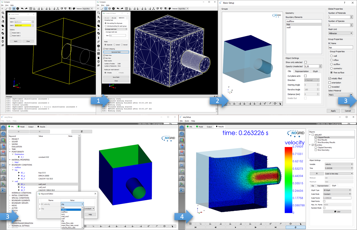
Steps from geometry generation to simulation results
TRAINING
Our two-day training courses teach participants how to set up, run and evaluate simulations efficiently with NOGRID CFD software. The courses include practical guidance for handling different types of simulation cases.
For more details please refer to Training Courses →
Technical Support
Professional support is available from the beginning of your work with NOGRID. Our technical team assists users by telephone and email with software operation, case setup and simulation-related questions.
For more details please refer to Software Support →
Simulation Service
When internal time, expertise or resources are limited, NOGRID can support your project with individual numerical simulation services. Our engineers develop and evaluate CFD models based on the specific requirements of your application.
For more details please refer to Software Support →